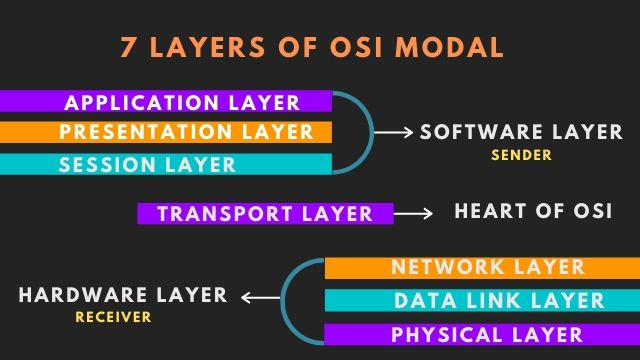
The OPEN SYSTEM INTERCONNECTION Model is a conceptual model.The characterize and standardizes the communication,functions of a telecommunication or computer system.
The OSI Model Defines a Networking Framework To Implement Protocols in Layers,with control passed from one layer to the next.
OSI was developed by the INTERNATIONAL ORGANIZATION FOR STANDARDIZATION and introduced in 1984.
It is layered architecture (consist of seven layers). Each layer defines a set of function in data communication .

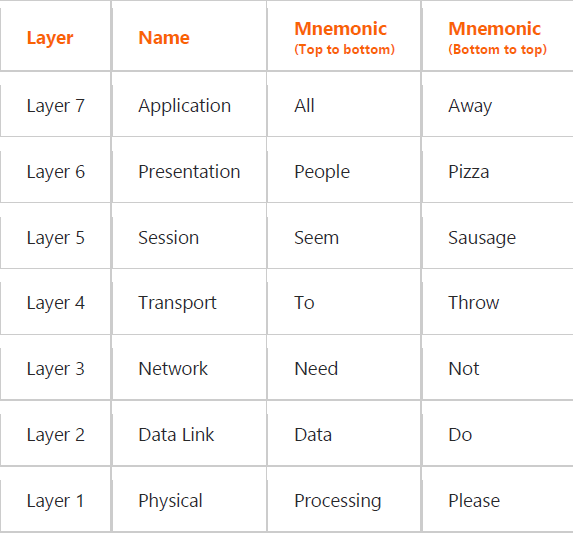
Remembering the OSI Model 7 layers
To help remember the layer names of the OSI model, try using one of the
following mnemonic devices:

Using The OSI Model To Discuss Networking Concepts
- Provides a common language or reference point between network professionals.
- Divides networking tasks into logical layers for easier comprehension.
- Allows specialization of features at different levels.
- Aids in troubleshooting
Define OSI Seven Layers
Layer 7 – Application
Application layer may be called as desktop layer. As it uses
browser,messengers & many more software which can easily transfer the data from end user to the network {PDU=DATA}
Layer 6 – Presentation
This layer received the data from application layer is converted as per the
required format of the data.Whether it is image /video/text format. the encryption (at the sender side) & decryption (at the receiver side) also takes places in this layer .{PDU=DATA}
Layer 5 – Session
This layer is responsible for establishment/termination of connection
through authentication i.e , login/logout & maintaining of session which
ensures security.{PDU=DATA}
Layer 4 – Transport
This layer received the formatted data from the upper layer & divide the data into small chunks which is known as segment of data.This layer is responsible for the end to end delivery of the complete message. The two protocol are used in transport layer are TCP&UDP. {PDU=SEGMENT}
Layer 3 – Network
Segments in network layer is referred as packets which includes sender IP address (source IP address) & receivers IP address (destination IP address)
that is placed in the header of the each packet. Networking devices used in this layer -Router,Multilayered switch {PDU=PACKET}
Layer 2 – Data Link
Packets in data link layer is referred as frames. After creating frames,DATA LINK Layer adds source mac address & destination mac address in the header of each frames.
Device used in this layer – switch {PDU=FRAME}
Layer 1 – Physical
This layer is responsible for the physical connection of the devices such as cabling. The physical layer contains information in the form of bits (0,1) {PDU=BITS & BYTES}


